Third Carquinez Strait Bridge
Background
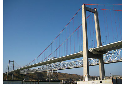
The Carquinez Strait, located about twenty miles northeast of San Francisco, carries the Sacramento River into San Francisco Bay. The strait was originally spanned by two steel truss bridges, built in 1927 and 1958, that provide a vital link on the Interstate Highway 80 corridor.
Heavy traffic on I-80, along with the infeasibility of adding lanes to the existing bridges, led to planning and engineering studies for a third bridge. Regional Measure 1, a 1988 ballot initiative in the San Francisco Bay Area, implemented higher bridge tolls to fund various projects including a new bridge at this site.
The need for a new crossing became more compelling when engineering studies of the 1927 structure showed that it was highly vulnerable to seismic damage, and that retrofitting it to current standards could be nearly as costly as building a new bridge. At the same time, the high estimated costs for retrofitting all of the areas toll bridges make an economical structure even more imperative.
In the mid-1990's, an 1175 ft span cable-stayed bridge was studied under a Caltrans contract. The structure would have three towers, each extending about 260 ft above the navigation profile, or about 90 ft taller than the truss. This bridge would require significant marine-based construction at the center pier.
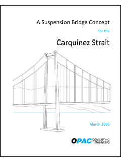
However, OPAC believed a suspension bridge would present an aesthetic and potentially economical alternative to the proposed three-tower cable-stayed bridge for the third Carquinez Strait crossing. It is a classical structural form that would be more aesthetically compatible with the existing bridges than a cable-stayed bridge. Construction could proceed very rapidly with only two river foundations, modern parallel-wire prefabricated cables, and a composite box girder deck. Also, it eliminates a potential hazard to navigation at the center pier.
Another compelling argument in favor of a suspension bridge is seismic behavior and performance. Seismic studies of suspension and cable-stayed bridges suggest that seismic demands on the towers are dominated by inertial forces originating in the towers themselves. Therefore, eliminating the center tower virtually eliminates a third of the seismic demands and therefore provides a substantial savings in achieving seismic resistance.
In 1996, OPAC initiated some design studies on a suspension bridge to satisfy our own curiosity. The studies are summarized in a report entitled A Suspension Bridge Concept for the Carquinez Strait, dated March 18, 1996, by OPAC Consulting Engineers. The report focused on three basic aspects of the design process:
- The bridge concept and its essential structural features,
- Analytical studies that demonstrate its performance, and
- A construction procedure and anticipated construction cost.

OPAC's Conceptual Bridge Layout
The studies by OPAC demonstrated the validity of the suspension bridge concept for the Carquinez site. The studies unequivocally showed that using modern construction technology, a bridge form that was brought to the forefront of long-span construction by American innovation and expertise can provide an aesthetic and economic solution at this location. OPAC presented the report to Caltrans in September of 1996, when Kwong Cheng and Mark Ketchum met with Jim Roberts, Caltrans director at the time.
Type Selection
Further structural studies for the new bridge, conducted by Caltrans and other consultants, addressed design, construction, and cost of cable-stayed, suspension, arch, and truss alternatives for the new bridge, and demolition of the existing 1927 bridge, took place in 1997. These studies concluded that further engineering work was warranted on both cable stayed and suspension bridge alternatives.
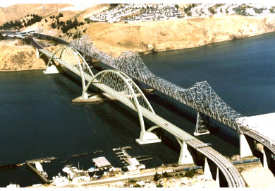
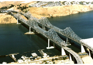
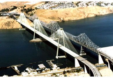
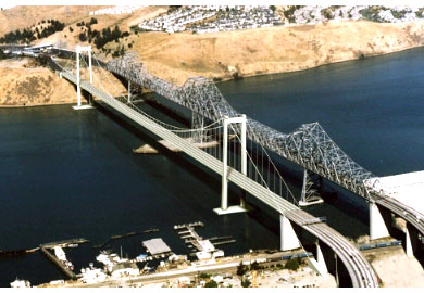
In 1997, Caltrans engaged the DeLeuw-OPAC-Steinman, Joint Venture for the advanced engineering work, to conclude with final design and construction of one of these bridge types. The Joint Venture prepared plans, Special Provisions and construction estimates for the new bridge and for the demolition of the 1927 main span. The bridge type selection considered both the cable-stayed bridge and suspension bridge as possible structure types for final construction.
Suspension Bridge Alternatives
The suspension bridge alternatives consist of a single main span across the navigation chan-nels, supported on towers located adjacent to the north and south piers of the existing truss bridges. The suspension bridge eliminates the mid-river foundation and tower of the cable stayed bridge, but requires a much longer span as well as cable anchorages at each side of the river. Two different span layout options and two different superstructure options were investigated. The span layout options consist of 1) a symmetrical bridge with short side spans at each end, and 2) an unsymmetrical bridge with a longer side span to cross the railroad tracks at the south end. The superstructure options consist of 1) a closed orthotropic steel box girder design, and 2) a composite edge girder design.The towers for the suspension bridge alternatives are batter-leg, two-bay reinforced concrete portal frames. Several different tower configurations were considered in the initial studies, including steel and concrete portal towers with two or three struts, and cross-braced towers. The system provides adequate transverse resistance, a constructable system, and manageable seismic demands. The batter allows the shafts to clear the edges of the girder and still provide cable spacing compatible with the deck width. These towers will behave longitudinally as propped cantilevers, and transversely as moment resisting frames. The tower foundations consist of multiple, 3.05 m (10 ft) diameter cast in steel shell (CISS) piles. The piles are socketed into the rock and embedded into their caps, with reinforcement to develop moment-resisting connections. The cast-in-place pile caps use precast forms that also would serve as pile templates. A total of 12 piles is required for each of the north and south towers.Findings on the Suspension Bridge Alternatives
Conceptual design studies, followed by preliminary design and engineering studies, were performed on a suspension bridge alternative. Two different superstructure options were investigated at the conceptual design level:
- a closed orthotropic steel box girder design, and
- a composite edge girder design.
The recommended superstructure is the closed orthotropic steel box girder design. It requires smaller cables and anchorages than the composite option, provides better seismic performance, is a more proven structural system, and could be somewhat faster to build. Two different span layout options were investigated at the preliminary design level:
- a symmetrical bridge with short side spans at each end, and
- an unsymmetrical bridge with a longer side span on the south end.
The recommended span layout is the symmetrical bridge option. It eliminates some ramp alignment problems by keeping the end of the suspension bridge farther north. It is considered aesthetically superior. It has less potential interference with utilities and a smaller hazardous materials footprint. The construction cost estimates also support this choice.
Cable Stayed Bridge Alternatives
The cable stayed bridge alternatives for the third Carquinez Strait bridge consist of two main spans across the navigation channels, supported on three main towers located adjacent to the three piers of the existing bridges. The cable stayed bridge requires a mid-river foundation and tower, but eliminates the longer span and the cable anchorages of the suspension bridge To match the spans of the existing three tower truss bridges at Carquinez Strait, the proposed cable stayed bridge span configuration is 150 m (492 ft), 364 m (1194 ft), 364 m (1194 ft), and 150 m (492 ft). The bridge is aligned approximately 46 m (150 ft) downstream of the ex-isting southbound (1927) structure. Two different superstructure options and two different stiffening options for the center tower were investigated. The superstructure options consist of 1) a composite concrete deck with steel edge girders, and 2) a post tensioned concrete deck with concrete edge girders. The primary structural differences between these two options are the deck cross section, cable size, and foundation sizes. The stiffening options for the center tower consist of 1) a girder-stiffened center tower, in which the stiffness of the girder and its connections to the towers stabilize the center tower, and 2) a braced, split-leg center tower, in which the shafts of the center tower are splayed longitudinally to provide its stability.
Findings on Cable Stayed Bridge Alternatives
Preliminary design and engineering studies were performed on a cable stayed bridge alternative. Two different mid-river tower stabilization options and two different superstructure options were investigated. The mid-river tower stabilization options consist of
- a girder-stiffened tower utilizing a moment connection with the girder, and
- a tower-stiffened option utilizing a longitudinally braced tower.
The recommended tower stabilization option is the tower-stiffened scheme. It provides much better superstructure performance under service loads, as well as reduced seismic demands on the tower shafts and foundations. Seismically, it takes better advantage of the long period nature of the cable supported bridge. It also allows several schemes for improving seismic capacity should the demands increase due to alternative ground motions. Unlike the girder stiffened scheme, energy dissipation technology could be readily applied to the tower stiffened scheme. The superstructure options consist of
- a concrete edge girder design, and
- a composite edge girder design.
The recommended superstructure is the concrete edge girder design. It requires more cables than the composite option, but its long term maintenance requirements are lower.
Bridge Type Recommendation
The bridge type selection studies concluded that both bridge types were technically feasible, and within the context of the study parameters would cost approximately the same. Each alternative had particular advantages and disadvantages. However, the steel box girder suspension bridge was determined to represent a better value for the following reasons:
- Superior seismic performance,
- Shorter construction schedule,
- Less risk of ship impact due to fewer number of piers in the water,
- Less maintenance on cable system,
- Slightly better aesthetics,
- Less construction risk.
Following presentation of the Type Selection Report - Third Carquinez Bridge, dated Sep-tember 10, 1997, a selection committee consisting of Caltrans representatives was convened. The committee unanimously advanced the steel box girder suspension bridge into the final design phase.
Design
General Configuration
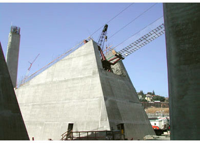
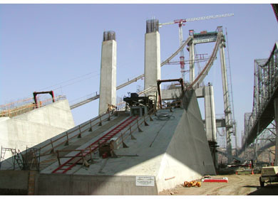
The alignment of the bridge is approximately 46 m west of the original 1927 bridge structure. The general span arrangement of the suspended superstructure, as shown below, consists of a 147 m south side-span, a 728 m main span and a north side-span of 181 m. On the south, the main cables pass through the upper portion of a reinforced concrete pier, span over the existing Union Pacific Rail Road (UPRR) and enter a gravity anchorage near the existing grade line. To the north, the main cables enter directly into the gravity anchorage located on top of the bluff along the northerly coastline of the Carquinez Strait. The north anchorage location was restricted by the existence of an ancient landslide slip plane near the edge of the bluff and the Pacific Gas and Electric transmission tower near the northeast corner of the anchorage.

Final Bridge Layout
In general, the bridge is on an uphill grade from south to north. The southernmost grade is +1.9 percent leading to a vertical curve within the main span of the structure. To the north of the vertical curve, the roadway descends gradually on a grade of -1.1 percent. The roadway is on a 2 percent cross slope from the north anchorage to the transition pier located adjacent to the UPRR.
Design Basis
Final Tower Layout
The following design codes were used:
- Caltrans Bridge Design Specifications (BDS), 1995 (AASHTO with Revisions by Caltrans)
- Caltrans Seismic Bridge Analysis Package
- Caltrans Memos to Designers
- Caltrans Bridge Design Details
- Caltrans Bridge Design Aids
- Caltrans Information and Procedures Guide
- AASHTO Guide Specification for Vessel Collision Design, 1991
- AASHTO Segmental Bridge Specification, 1989
- AASHTO Guide Specifications for Thermal Effects in Concrete Bridge Members, 1989
- AASHTO LRFD Bridge Design Specifications, 1994
- ACI 318-95/318R-95 Building Code Requirements for Structural Concrete and Commentary (Torsion Provisions)
- ANSI / AASHTO / AWS D1.5-96, Bridge Welding Code
- ANSI / ASCE 7-88, Minimum Design Loads for Buildings and Other Structures, 1990 (for Preliminary Wind Loads)
- CEB-FIP Model Code for Concrete Structures, 19th Edition, for Time Dependent Behavior of Concrete only
- FHWA Hydraulic Engineering Circular No. 18, Evaluating Scour at Bridges, FHWA-IP-90-017, 2nd Edition, February 1993
- PTI Recommendations for stay cable design, testing, and installation, 1992
- Caltrans Standard Specifications, July 1995
- AASHTO Segmental Bridge Specification, 1989
- PTI Recommendations for stay cable design, testing, and installation, 1992
Wind Loads
Both static and dynamic wind effects were considered. For Preliminary Design, static wind load was based on ANSI/ASCE 7-88. Dynamic wind effects were considered using qualitative methods only. Final design made use of wind tunnel tests of section models to determine drag, lift, and flutter coefficients for the superstructure and tower cross sections. These were used in dynamic analyses of computer models of the structure to evaluate the critical wind speed for flutter and the magnitude of buffeting to be expected at the design wind velocity. The design wind speed was based on the 100-year return period wind speed for the site. The critical wind speed for initiation of flutter was set to be no less than either 1.2 times the 100-year return period wind speed, or 150 mph. Wind effects during construction stages were investigated to assure stability of the bridge in critical partially-completed forms.Seismic Loads
Seismic design of the bridge is governed by the Caltrans Seismic Performance Criteria for the Design and Evaluation of Bridges (1/4/95). It was subjected to a two-level evaluation:- A safety evaluation, underground motions corresponding to a maximum credible event with a return period of 1000-2000 years (Safety Evaluation Earthquake or SEE), for which the bridge can be subject to damage only if it can be classified as repairable.
- A functional evaluation, underground motions corresponding to an event with a return period of 285-300 years (Functional Evaluation Earthquake or FEE), for which the bridge can be subject to damage only if it can be classified as minor.
This is higher than the minimum level required for all transportation structures but below that required for an important bridge. As much as possible, the Important Bridge criteria are to be met.
Steel Box Girder Design
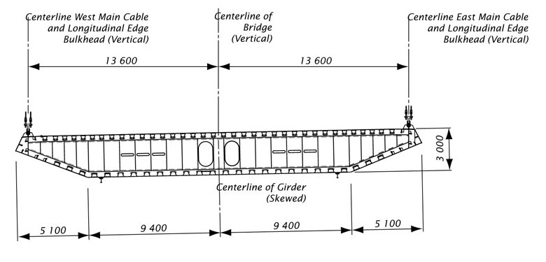
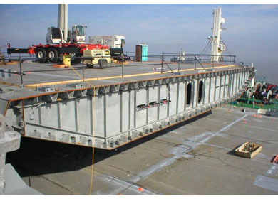
The suspended superstructure of the new Carquinez Bridge consists of a closed steel box girder. The girder is continuous from the north anchorage to the transition pier at the south, resulting in a total girder length of 1056 m. All fabricated structural steel components of the box girder, including the bulkheads, are to be of Grade 345 MPa steel. The box girder cross section is 3 m deep and 29 m wide. The edge plate and side plates are shaped as necessary to provide an aerodynamically stable cross section.Longitudinal bulkhead plates are provided to improve the vertical shear carrying capacity of the box girder and to accommodate seismic demands resulting in large bending moments about the vertical axis of the girder.
Typical Box Girder Cross Section
The orthotropic deck of the box girder consists of a 16 mm deck plate with longitudinal 305 mm deep hermetically sealed trapezoidal closed ribs fabricated from 8 mm thick bent plates. Transverse bulkheads are spaced at 6.2 m intervals.
Vertical supports for the box girder are prescribed at the towers, at the north anchorage and at the transition pier with rocker links.
Cable System Design
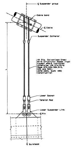
Suspender Detail
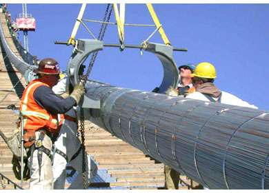
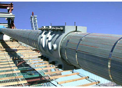
Each main cable consists of 8,584 zinc coated carbon steel wires, compacted to a diameter of 512 mm, and wrapped with galvanized steel wire. The No. 6 gage cold drawn wire has a specified minimum ultimate tensile strength of 1,570 N/mm2 (228 ksi), a minimum yield strength of 1180 N/mm2 (170 ksi), and a maximum allowable working stress of 690 N/mm2 (100 ksi). The cable corrosion protection system consists of an elastomeric zinc-rich paste, galvanized wire wrapping and high-elasticity acrylic paint system. The suspenders are also protected with the same paint system as the main cables.
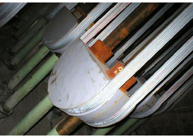
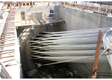
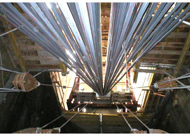
In the anchor chambers, the main cables splay into 37 individual strands. Each strand is secured around strand shoes that are fixed in place by steel rods embedded within the anchor blocks. This design approach is consistent with the air spinning method of cable construction selected by the contractor.
The vertical suspenders that carry loads from the suspended roadway to the main cables are zinc-coated steel structural wire ropes at a typical spacing of 12.4 m along each side of the girder. Resin socketing to the end fastenings was selected over the traditional spelter method to provide improved fatigue performance and better corrosion resistance at the nose of the socket cones. External linkage assemblies connecting the suspenders to the box girder provide a maintainable and inspectable system.
Suspenders are designed with a factor of safety of 4.0 against the ultimate breaking strength. Redundancy is provided by including a pair of suspender ropes at each connection point plus consideration for the possible loss of one suspender group.
Cable Anchorage Design
The two cable anchorages are significantly different in configuration, due to the bridge geometry and the dramatically different site conditions. The north anchorage was perched on a rock bluff overlooking the Carquinez Straits. An integrated anchorage and abutment was located back from the bluff face to avoid a shear zone that was discovered during geological studies. The top of the bluff was benched to allow the bridge girder to span to the abutment. Twin anchor blocks, one for each cable, were embedded in the rock below the existing ground and future roadway. Resistance to lateral cable forces was provided by base friction and passive resistance on the anchor blocks. To enhance the lateral resistance, the two north anchor blocks were connected by a massive grade beam.
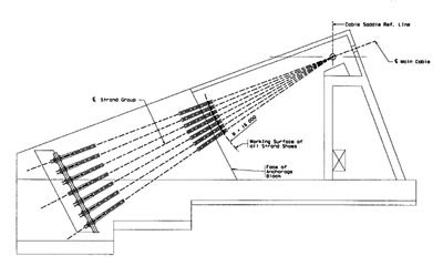
South Anchorage
The south anchorage is located below the new approach viaduct, well south of the transition pier, on soft bay mud overlaying weak claystone/siltstone. The location was determined in part by the geometrical constraints of the Union Pacific tracks and the existing 1927 bridge approach foundations. The cable splay housings and a portion of the anchor block are above ground, with the remaining anchor block and foundation below grade. Vertical support and lateral resistance are provided by 380 steel shell piles of 760 mm diameter that are driven into the claystone material and filled with concrete. Of these, 171 are vertical and 209 are placed on a batter of 1 horizontal to 3 vertical.
Center-Tie Design
A center cable tie is incorporated into the design to improve aerodynamic performance. The increase in structure stiffness with regard to anti-symmetric torsional vibrations will improve the performance of the bridge.The center-tie design also has other advantages in that it protects the short suspenders near mid-span from fatigue damage resulting from bending stresses that develop near the end attachments of the suspender cables. It also serves to transmit longitudinal forces to the main cables helping to resist drift of the suspended girder towards either anchorage. This action also counteracts the destabilizing forces on the rocker links, which because they are compression links would otherwise have an additive effect on girder drift tendencies.
The component design of the center tie, though introduced for the described reasons, was predo-minately controlled by seismic demands. Each component was in general designed to resist the SEE event with essentially elastic response. The cable clamp component was designed to resist the full SEE demands without slippage.
Tower Design
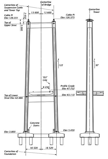
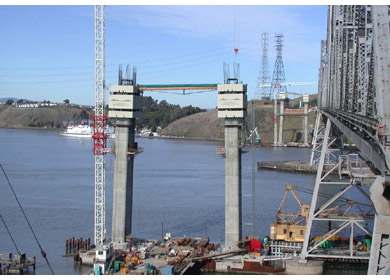
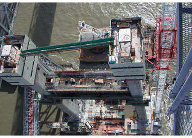
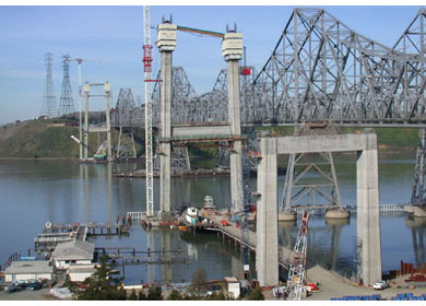
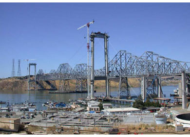
The concrete towers are of portal configuration with slightly battered shafts. The battered geometry allows the box girder to pass unobstructed between the tower shafts, while keeping the cable saddles concentric with the shafts and the cable catenaries vertical. The hollow shafts have a constant 3.75 m width and are symmetrically inclined inwards at a rate of approximately 1 in 40. When viewed in the longitudinal direction, the tower shafts taper from 8.25 m at the base to 5.8 m at the top. Each tower leg is made integral with the reinforced concrete pile caps at the base. Just above the water line, the matching pair of pile caps are connected by a reinforced concrete tie-beam. Each tower has two prestressed concrete struts, one below the deck and the other near the top. The tower legs have been detailed to have flexural ductility capacities that considerably exceed their ductility demands and thereby ensure seismic safety even if earthquake effects are greater than predicted. Each tower has two struts, the lower strut is below the superstructure and the upper strut is at the top of the tower. Both struts are post-tensioned concrete boxes.Tower Foundation Design
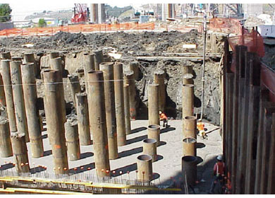
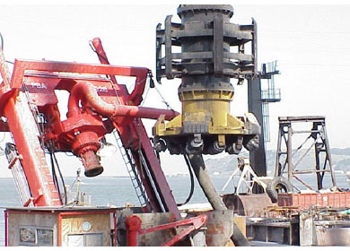
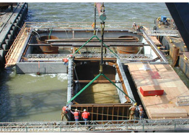
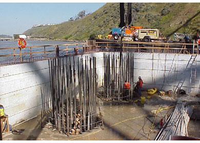
Each tower is supported by reinforced concrete pile caps under each tower leg. Each pile cap is supported by six 3000 mm cast-in-steel shell concrete piles, with the caps connected by a tie beam. The piles consist of a 3m diameter, 45 mm thick steel casing driven to rock. The casings are 47.25 meters long at the south tower, and up to 38.45 meters long at the north tower. The casings were then cleaned out and a 2.7m diameter rock socket is drilled beyond the tip of the casing. The rock sockets are 44.70m long at the south tower and between 16.20m and 24.2m long at the north tower. The rock sockets and steel casings were then reinforced and concreted using tremmie methods.South Viaduct Design
At its south end, the suspension bridge connects to a new curved approach viaduct. The south end of the suspended span and the north end of the new approach viaduct are supported on a transition pier, which was configured to aesthetically match the bridge towers. The transition pier also houses the cable tie-down. The pier is supported on 760 mm steel shell piles filled with concrete.Analysis
Dead Load Analysis
A multi-stage dead load analysis was performed with a non-linear 2-D model, as means of attaining the final dead load deck profile grade with the correct distribution of load in the suspenders. The purpose of the procedure was to ensure zero global bending moment in the box girder at the design dead load at standard temperature.
A separate model consisting of cable elements only was used to evaluate the free cable geometry immediately following cable erection. The purpose of this analysis was to support the saddle design effort, determine the extent of tower pull-back during main cable erection, and to evaluate the pre-dead load geometry of the tie-downs.
Live Load Analysis
Live load cases were generated using the following conditions:- For the box girder: Loaded length that produces maximum positive shear and negative shear, maximum positive bending moment, and maximum negative bending moment.
- For the towers: Loaded length that produces the maximum axial force, maximum positive bending moment, and maximum negative bending moment.
- For the cables, tie down, and rocker links: Loaded length that produces the maximum positive axial force and maximum negative axial force.
A separate load analysis was undertaken to evaluate explicitly the torsional response of the box girder.
Temperature Change Analysis
Temperature demands in the box girder, cables, suspenders, and towers were evaluated by applying a uniform thermal loading to all components, except piles and foundation. A uniform temperature rise or fall of 22°C (steel) and 16°C (concrete) from 27°C mean temperature was used in accordance with Caltrans BDS.
A temperature gradient of 11°C between the top and bottom of the orthotropic box girder was applied in accordance with the Project Design Criteria.
3D Finite Element Analysis
3D finite element models were used to evaluate the rib stresses in both the orthotropic deck ribs as well as other box stiffening ribs for strength and fatigue. Fatigue stresses in the orthotropic deck ribs were evaluated at the field deck plate splice, the diaphragm rib cut-out and other locations as necessary. The finite element models consist of a combination of plates and beam elements. All the ribs are modeled as beam elements and all the bulkheads and box skin plates are modeled as plate elements.
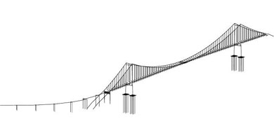
Global 3D Model
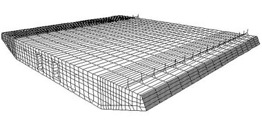
Finite Element Model
Wind Evaluation
Wind evaluations of the bridge were undertaken to refine the design of the bridge, and to establish its safety and stability in the wind environment of the site. The goals of the studies were to establish the design wind environment, provide input to the designers in the final shape of the suspended structure, and to estimate the static and dynamic response of the bridge in various wind conditions. The evaluations consisted of the following components:
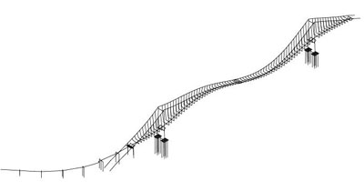
Longitudinal Mode Shape
- Review of historical wind data to establish a design wind speed and a critical flutter threshold wind speed for design of the bridge. The 100-year recurrence, one-hour averaged, design wind speed at deck elevation was determined to be about 47 m/sec (105 mph). The critical flutter threshold, 10 minute average, wind speed at deck elevation was determined to be about 70 m/sec (157 mph).
- Wind tunnel studies of section models of the steel box girder superstructure to determine its static drag, lift, and toque coefficients and its aerodynamic flutter derivatives. These studies were done in two phases. The initial phase consisted of approximate studies to determine the relative influences of girder shape and railing configurations on static and dynamic performance. The final phase made use of refined high-precision models for evaluation of final static and dynamic coefficients to be used in static and dynamic response analysis. Due to the cross-slope of the bridge deck, the models were evaluated separately to determine the effects of easterly and westerly winds.
- Wind tunnel studies of a model of the complete bridge to determine the influence of the existing bridges on the static and dynamic wind performance of the new bridge and to validate the analytical modeling of turbulence effects.
- Wind tunnel studies of a model of a short segment of a tower shaft to evaluate its drag coefficients under transverse, longitudinal, and skewed wind.
- Wind tunnel studies of a model of a free-standing tower to evaluate the static and dynamic wind-induced response of the tower to naturally occurring turbulent winds during the construction phase.
- Development of a 3D dynamic computer model of the complete bridge structure including the south viaduct. It was used to evaluate the dynamic modal properties of the bridge for use in the flutter and buffeting analyses, to evaluate the stresses in the bridge due to static wind drag, and to evaluate stresses in the bridge due to dynamic modal contributions from the buffeting analysis.
- Static analysis of the computer model to evaluate the steady-state components of bridge displacements and stresses due to a) longitudinal wind load, b) transverse wind load, c) skewed wind load and d) wind on live load. The loadings were derived from the drag coefficients provided by the wind tunnel tests of the tower and deck cross sections (for a, b), by vector combinations of the drag coefficients (for c), and from Caltrans BDS 3.15.2.1.2 scaled to the design wind speed (for d).
- Dynamic analysis of the computer model to evaluate frequencies and mode shapes of the first fifty vibration modes of the bridge. The modal characteristics were extracted using standard eigenvalue solution procedures for finite element problems. The mass-normalized mode shapes were then integrated over the length of the bridge to provide data of the form required for the flutter and buffeting analyses. The frequencies of these modes varied from 0.15 Hz to 1.08 Hz.
- Aerodynamic stability evaluation to determine the threshold wind velocity at which single-mode or coupled-mode flutter instability would occur. This was performed using aerodynamics theory incorporating the flutter derivatives derived from the section model, and the vibration characteristics from the vibration analysis, considering 50 vibration modes and 0.3% structural damping. The lowest threshold wind velocity was found to be 163 mph.
- Buffeting analysis to determine the dynamic components of displacements and stresses in the bridge when subjected to velocity fluctuations in the transverse wind. The procedure provided probable maxima of modal displacement response in the first fifty bridge modes. Eleven dominant modes were identified. The probable maxima of total bridge response - displacements and stresses - were found by combining the modal contributions by the SRSS method.
- Evaluation of gust factors using the basic approach of ASCE/ANSI 7, to relate total (static + dynamic) response to the static response. These factors were determined for a components and directions of wind except transverse wind on the deck, for which a similar relationship was defined in the buffeting analysis. Gust factors for most components ranged from 1.8 to 2.0.
Seismic Analysis
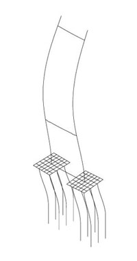
Stand Alone Mode Shape
A seismic evaluation of the bridge was undertaken to support its design and to demonstrate compliance with the Design Criteria. The evaluation consisted of the following components:
- Seismic hazard assessment, to assess response spectra for the underlying rock at the site, representative of the Safety Evaluation Earthquake (SEE) and the Functional Evaluation Earthquake (FEE).
- Development of rock motion time histories at each support location of the bridge, corresponding to the SEE, that are compatible with the design response spectra, incorporate near-fault effects, and include spatial variations over the length of the bridge. Three sets of rock motions were developed, representing three different SEE events. One of these was scaled to represent a FEE event.
- Site response analyses at each support location of the bridge, under each of the three sets of SEE rock motions, to incorporate the effects of local subsurface conditions on the ground motions at each support.
- Development and analysis of Soil-Structure Interaction computer models for each of the foundations of the bridge.
- Development of 3D nonlinear computer models of the bridge structure above the rock line. The models account for the dynamic properties of the superstructure and substructure, important nonlinearities including geometric nonlinearities and inelastic component behavior, and interaction between the foundations and the surrounding soil.
- Analysis of the bridge model under ground motion input, in order to determine critical bridge response. The analyses include linear response spectrum analyses, plus linear and nonlinear time-history analyses with multi-support ground motion input. The nonlinear time-history analyses were performed for the three sets of SEE motions, and also for one of the SEE motions but with the soil scoured to half its maximum scour, and for one set of FEE motions approximated by scaling the SEE motions by 0.6.
- Determination of demand and capacity values for forces and deformations at critical locations. The design of the bridge was refined over the course of the design project so that the demands and capacities conform to the Design Criteria.
Design Validation
Structural performance of the new bridge was studied and validated in numerous engineering studies using computer and physical models. The most significant efforts were expended in seismic and wind evaluations.
Design validation for seismic conditions was one of the significant challenges of the project. Seismic performance evaluations of the bridge made use of global inelastic dynamic computer models of the entire bridge, supported by detailed computer models of local conditions, components and subassemblies.
The 3D global model represented the entire bridge from anchorage to anchorage, and included the effects of inelastic component performance and soil-foundation-structure interaction. The varying geotechnical conditions along the length of the bridge were considered by incorporating representations of the underlying soil and rock into the computer model of the bridge, and exciting the different supports with different ground motions. Inelastic modeling of critical components allowed accurate prediction of deformations and strains under SEE and FEE earthquake motions. Considerable design refinement resulted from these studies, particularly in the towers and foundations where it was found that adding strength was sometimes fruitless if additional mass was required to provide the strength.
Local component models of the steel box girder, the pile caps, and the tower sections provided insight into their performance and detailing. The box girder is not a compact section, and is subjected to considerable warping and distortion stresses. The pile caps and tower shaft sections are critical to seismic performance and were refined using inelastic finite element modeling.
Design validation for wind conditions made use of wind tunnel tests and computer modeling. Preliminary wind tunnel tests of large-scale section models allowed refinement of the box girder and railing shapes for optimal wind performance. Further tests of section models, supported by dynamic computer analyses, validated the design with respect to flutter (the instability that occurred at Tacoma Narrows) and buffeting. A full bridge model was tested in the wind tunnel to evaluate the influences of the existing bridges and the distribution of wind velocities across the strait.
Both the seismic evaluation and the wind evaluation supported the design of all bridge components and demonstrated that the bridge is in compliance with the design criteria.
Construction
A construction sequence was developed to confirm the design assumptions. In general terms, construction of the approach spans includes land-based foundation construction, cast-in-place reinforced concrete piers and abutments, and a cast-on-falsework multi-celled post-tensioned concrete superstructure.
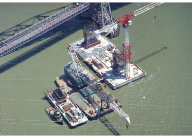
Construction of the main span includes marine-based foundation construction, marine-based construction of reinforced concrete towers, land-based construction of the anchorage housings, erection of the cable system, and erection of the steel deck.
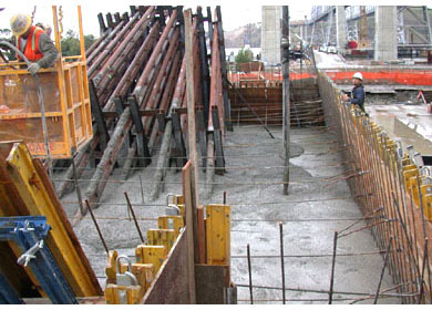
The tower footing forms are precast, prestressed concrete elements that were floated into place and used as driving templates for installation of the 3000 mm cast-in-steel shell concrete piles. Once all the tower piles were installed, the tie beam form was placed and the complete footing form dewatered to allow placement of the footing reinforcement and concrete in a dry environment. Flotation sleeves were also removed and the footing form supported by internal framing and hanger rods. The construction of the towers used conventional slip-forming method.
The following arrangements were used for the construction of the cable systems and superstructure:
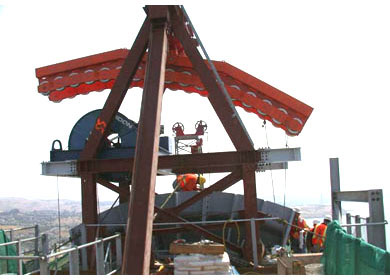
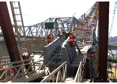
- Cathead frames were mounted on top of each tower to bring the haul line across over the tower and later used to lift the saddles.
- The towers were pulled back using tie-back strands to allow for spinning the cable wires under balanced tension.
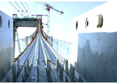
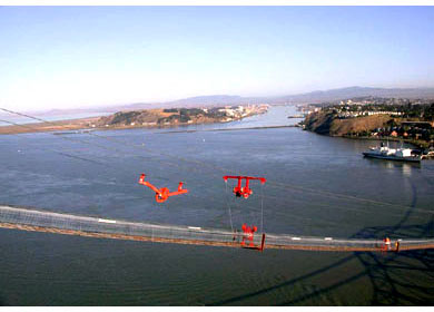
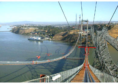
- Temporary aerial walkways were constructed to provide access to the main cable during the spinning and other suspension system erection operations.
- A storm system consisting of strands connected to the walkway and anchored at the main towers/existing center pier fender were constructed to brace the walkway against wind.
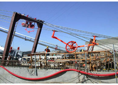
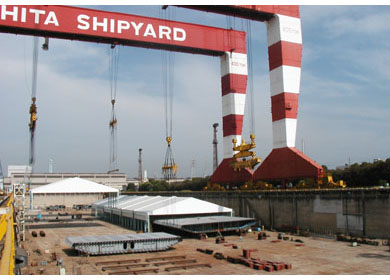
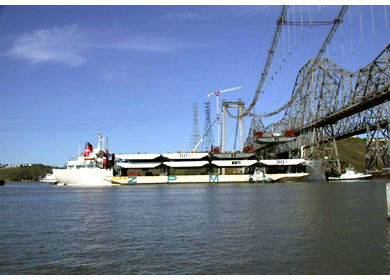
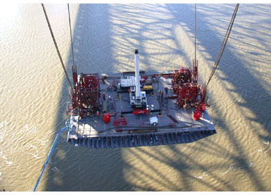
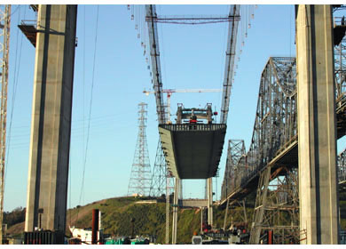
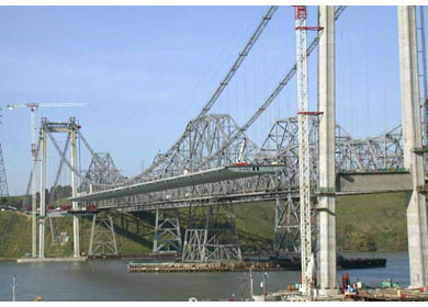
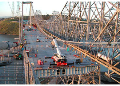
- The box girder segments were lifted into position from barges, using rolling gantry cranes mounted on the main cables. The center segments were the first segments to be lifted.
Foundation
Towers
Anchorages
Cables
Deck
Conclusion
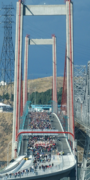
Opening Day
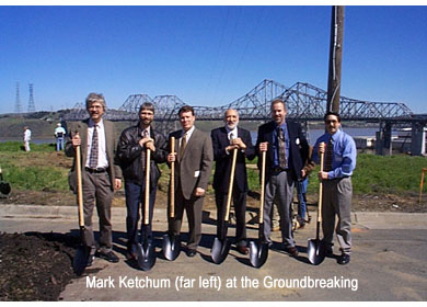
The design of the new Carquinez Bridge was completed in accordance with the applicable design codes and project specific design criteria. The bridge was designed to meet the appropriate seismic and wind design events, and to provide an estimated service life of 150 years. Groundbreaking ceremonies for bridge construction took place on March 3, 2000. Following a 1000 day construction schedule, the Joint Venture of FCI and Cleveland Bridge Corporation completed this third crossing at the Carquinez Strait, California. The original 1927 bridge was then removed.
The design of the new Carquinez Bridge sets a new standard in modern suspension bridge design in the United States, particularly with respect to seismic safety. Included are the latest advances in fatigue resistant details, concrete tower design and analytical approach to engineering.
This bridge renders the classical suspension bridge form with innovative design and construction technology and implements a number of firsts in North American bridge engineering. It is the first major new suspension bridge to be built in the United States since the Chesapeake Bay Bridge in 1973. The new bridge also features such innovations as:
- Use of large diameter (10 feet) piles for the foundations in lieu of the more traditional caisson.
- First use of concrete tower in a high seismic region.
- First use of a steel orthotropic box girder on a suspension bridge in the United States. The box girder has many advantages over truss-stiffened suspension spans of a more traditional type, including lower steel costs and lower maintenance costs, since much of the steel surface is sheltered within the section. In addition the height of the bridge can be reduced because of lower depth requirements. The smooth exterior makes painting easy and resists corrosion.
- Lower suspender connection designed for easy access, durability, and replacement under service conditions.
The completion of the new bridge, combined with the seismic upgrade of the 1958 truss bridge, upgraded an important transportation link across the Sacramento River. The new Carquinez Bridge increases the westbound traffic lanes from three to four to accommodate anticipated increases in traffic, and provides a spacious pedestrian/bike travel way. The pedestrian/bike travel way is a vital link in the long-range plan to establish a Bay Trail that encircles the San Francisco Bay. If needed in the future, the bridge can accommodate light rail vehicles as well.
The new Carquinez Bridge is viewed as a landmark for the community of Crockett, located immediately south of the bridge. The community has rallied behind the project, making it a focal point for their plans to make Crockett a more noteworthy locale.