Nanning Bridge
Background

Nanning City, the capital of the Guangxi Zhuang Autonomous Region, is the political, economic and cultural center of the region. It has long been recognized as a National Clean City and a National Garden City. Today, Nanning City is ranked as one of the top 50 cities for economical growth and becomes a major link between south and southwest economic zones in China. In a continuing effort to develop Nanning City into a modernized international city and to alleviate city traffic, the regional government has planned many improvements to its infrastructure system. The Nanning Bridge is one of the planned improvements.
In 1999, Vice Party Secretary Ma Qing Sheng of Guangxi visited Professor T. Y. Lin in San Francisco to discuss a new bridge for Nanning City. In early 2000, Professor Lin met with Nanning City Mayor Lin who expressed the desire to have a new bridge with a global vision. Professor Lin subsequently formed an association with OPAC to undertake the design of a new bridge.

Site Location
OPAC Principals have been colleagues of Professor Lin since the late 1970s. In September of 2000, the association of Lin Tung Yen & OPAC Consulting Engineers Inc. signed a contract with the Nanning City Development and Investment Company to provide complete engineering design services for the bridge. The Scope of Work includes the following:
- Concept development and type selection.
- Design & analysis of main structural elements.
- Final code check and preparation of working drawings.
The association later engaged two Chinese engineering firms to assist in the design efforts; they included the Advanced Consultancy of Guangzhou and the Transportation Design and Survey Institute of Sichuan Province.
The project organization of the project was as follows:
Professor T. Y. Lin served as Chief Engineer.
Kwong Cheng served as Project Manager.
Mark Ketchum served as Technical Leader.
Francis Drouillard served as Lead Concept Designer.
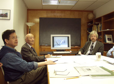
Professor Lin, Kwong Cheng and Mark Ketchum met with the Design Team.
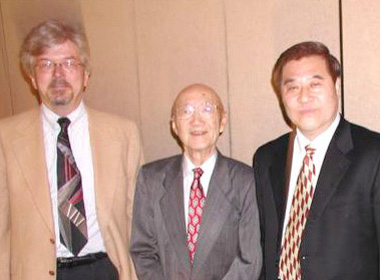
Prefessor Lin and Mark Ketchum met with Mayor Lin of Nanning.
Bridge Concepts
Bridge Type Selection Criteria
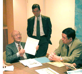
Professor Lin and Kwong Cheng presented design concepts to Vice Secretary Ma Qing Sheng of Guanxi.
In early 2000, the design team studied two basic alignments and profiles of the bridge from the project planning report prepared by the Fourth Survey & Design Institute of the Ministry of Railways, dated October, 1999. The entire bridge length is about 1050 m. This bridge is designed to carry six lanes of mixed traffic across the Yong River. A primary objective of the bridge design was to provide a unique bridge to satisfy the City's desire for a landmark, but with a rational and efficient form that meets performance and constructability requirements. The following criteria were considered in the development and selection of bridge concepts:
- Structural performance
- Aesthetics
- Applicability
- Constructibility
- Construction and maintenance costs
- Environmental impact
This part of the bridge type study is particularly important because of the potential landmark status of this bridge, which is needed to inspire public support. The various structural concepts that were evaluated consisted of variations on girder, arch, and cable-stayed systems. The bridge type selection process was conducted in two rounds.
Bridge Type Selection - Round 1
The following are some of the applicable schemes that were evaluated for this round:

Dorsal-Stay - The proposed main bridge consists of three spans, the center span having a length of 200 meters and the side spans having a length of 120 meters. With the external stiffening concrete stays, this scheme can adapt well to the constraints of the site, providing a stiff, strong bridge with a clean, efficient, and very modern appearance.
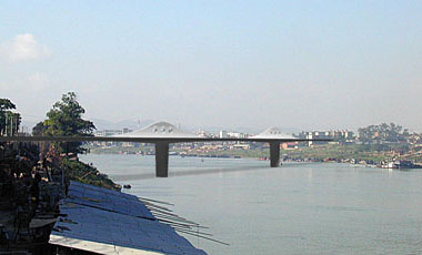
Dorsal-Spine - The proposed main bridge consists of three spans, the center span having a length of 200 meters and the side spans having a length of 120 meters. With the external stiffening concrete fins, this scheme can adapt well to the constraints of the site, providing a stiff, strong bridge with a unique, efficient, and classical appearance.

Cable-Stayed - The proposed main bridge has a main span of 200 meters and back spans of 100 meters. The single plane of stay cables was arranged in a fan shape. The reinforced concrete single column towers with cable along the center of the bridge deck, uniting at the tower heads with only one plane of cables, creates a modern and yet pleasing structure. The towers also display an impressive image.

Single Central Arch - The proposed main bridge consists of three spans, the center span having a 200 meter span semi-through arch. With a single central arch rib and strong structural elements for hangers to provide torsional stiffness, the traditional form of this scheme can adapt well to the constraints of the site, providing a stiff, strong bridge with a classical, and yet very modern appearance.
Round 1 Selection
All schemes were evaluated and compared with each other using the selection criteria. At the conclusion of Round 1, the Dorsal-Stayed bridge type was identified as the most applicable scheme.
Bridge Type Selection - Round 2
In mid -2000, at the request of Nanning City, additional concepts were developed to identify more potential landmark structures. The following are some of the applicable schemes that were evaluated for this round:
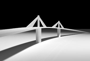
Dorsal-Stay - The proposed main bridge consists of three spans, the center span having a length of 200 meters and the side spans having a length of 120 meters. With the external stiffening concrete stays, this scheme can adapt well to the constraints of the site, providing a stiff, strong bridge with a clean, efficient, and very modern appearance.
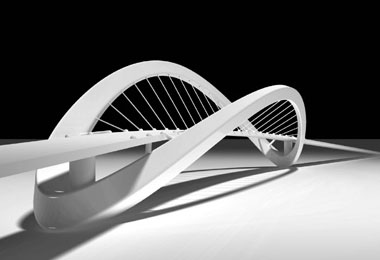
Arch with Asymmetric Ribs The main bridge consists of a horizontally curved steel box girder with a 300-meter span, supported by two independent inclined steel arch ribs. The 300 m main span provides adequate navigation clearance, and the inclined arch ribs support the curved deck as true arches, without significant out-of-plane bending.

One-Tower Cable-Stayed - The proposed main bridge has a main span of 250 meters and a back span of 140 meters. The stay cables were arranged in a fan shape. The A-shaped tower also displays an impressive image from a distance, blending in gracefully with the landscape.
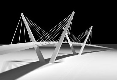
Two-Tower Cable-Stayed - The proposed main bridge has a main span of 200 meters and back spans of 100 meters. The double cable planes were arranged in an inclined fan shape. The reinforced concrete V-Shape towers with cables along the edge of the bridge deck, creates a modern and yet pleasing structure.
Round 2 Selection
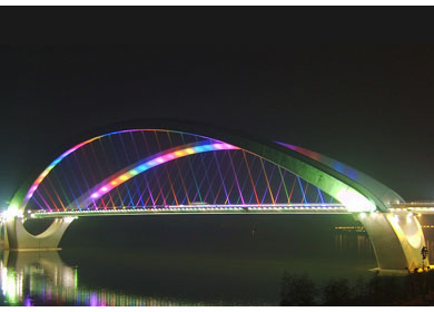
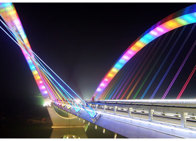
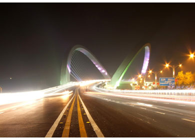
On the basis of bridge type selection studies, it was concluded that the Arch with Asymmetric Ribs would meet the requirements of the project. The design sets high aesthetic standards, and can be further enhanced with use of lighting, landscaping, and concrete finishing that reflect regional cultures. The Arch with Asymmetric Ribs was selected by the Nanning City government for the final design on November 29, 2000.Concept development of selected scheme
Prior to the final design, the design team performed additional design development in an effort to finalize the shape of the arch rib. The following were the two options: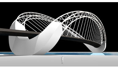
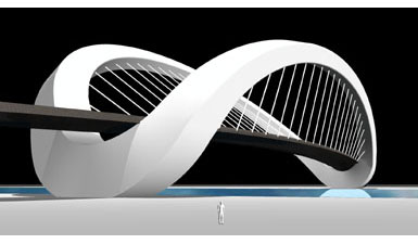

Truss Rib Option

Solid Rib Option
Final Selection
The solid arch rib option was selected for the final design.
Arch Geometry
Arch Geometry Development
The geometry of the inclined arch ribs was developed to provide a unique structural form, along with economy, constructability, and good performance under service conditions and extreme events. The arch rib geometry, both in plan and elevation, is subject to significant constraints in order to meet these goals and support the horizontally curved roadway geometry. They could not be simply drawn and designed; instead the profile, baseline-spacing, and angles of the ribs were specially developed to meet the structural requirements.
The arch shapes were developed so that they perform as true funicular forms, with dead load pressure lines oriented close to the centerlines of the ribs. This geometry helps assure that main load resistance is provided by compression in the ribs, and that bending and torsional loads on the ribs are relatively small. Technical criteria for shape development included:
- Roadway girder dead loads must be carried by the suspenders to the arch ribs, so that the girder is subjected to minimum bending moments.
- The arch ribs must be subject to minimum bending and torsion moments under the combined effects of dead loads, arch thrusts, and the restraint of the arch bases and roadway girder.
- The vertical and thrust loads on the arch foundations must be nearly centered on the foundations, so that the foundations are under minimum dead load overturning and torque.
- A balance must be reached between the height of the arch ribs, the magnitude of thrust to be resisted by the arch tie, the rigidity of the structural system, and the quantities of structural steel required for the arch ribs and tie.
- An aesthetically pleasing formation must result from the combined shapes of the arch ribs and the shapes formed by the suspenders.
- Constructibility must be achieved by maintaining simple curvature of each steel arch rib. Compound curvature is used only in the concrete arch bases.
The development of geometrical forms to meet these criteria was performed in three phases:
- A baseline form was developed using theoretical shape-finding computer programs.
- A refined form was developed using three-dimensional structural analysis of simplified computer models to better address aesthetic, clearance, and constructability issues.
- The final form was developed using refined three-dimensional structural analysis to optimize structural performance, particularly with respect to unbalanced lateral loads from the hangers on the horizontally curved deck girder.
Theoretical Shape-Finding
The shape-optimization studies used the principal of virtual displacements to derive arch rib forms that result in pure compression in the ribs under dead load and idealized support conditions. These studies concluded that the optimum rib shapes have the following features:
- Each rib lies in an inclined plane; a non-planar curve is not optimal. The incline angles of these planes depend on the relative weights of the deck girder and ribs.
- The rib on the outside of the curve lies in a plane about 5 degrees off vertical, so that in plan it follows the curvature of the roadway girder with slightly inclined suspenders.
- The rib on the inside of the curve lies in a plane about 30 degrees off vertical. The overturning due to the slope of this rib is offset by the horizontal pull of the suspenders.
- The rib on the inside of the curve is taller than the rib on the outside of the curve in order to reduce the eccentricity of the dead load weight and thrust on the foundations.
- The optimum shape of each rib in plan and elevation above deck level is of the catenary type and essentially parabolic.
The optimum shape of the arch ribs is shown in the following plots:

Plot of Plan View
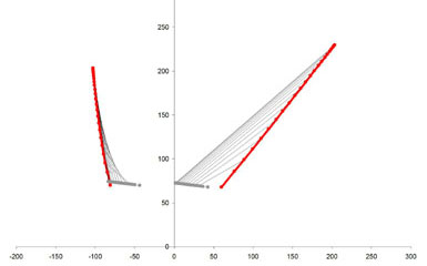
Plot of Transverse View
Design
Structure Description
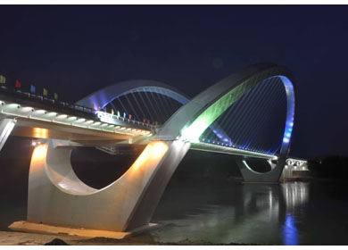
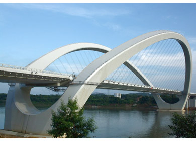
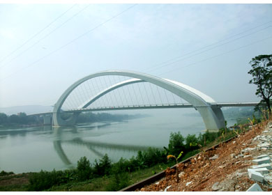
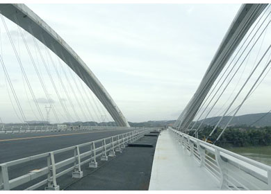
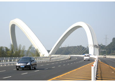
The principal feature of the bridge is its curved 300-meter main span. It is supported by two independent steel arch ribs, each on a separate inclined plane, with no bracing between the arches. The two arch ribs converge beneath the deck girder, and are separated widely at their crowns, to support the deck and control the three-dimensional flow of forces. The arch thrust is resisted by a steel cable tie housed within the steel box girder deck.


Bridge Elevation and Plan

Bridge Section
The arch ribs are supported on two arch bases that deliver loads to the foundations and provide visual continuity. These arch bases serve as inclined piers that support the tied arch span. They are designed to connect the arch ribs, roadway girders, foundations, and approach viaducts, to anchor the post tensioned arch tie that is within the deck girder, and to serve as the structural and architectural transition among them.
The approach viaducts are continuous post-tensioned concrete multi-cell box girders. The north approach has spans of 40m, 50m and 55m. The south approach has spans of 30m, 40m, 50m, 55m and 55m. The arch span and the approach viaducts form a continuous structure from abutment to abutment.
Design Basis
Design of the bridge followed the Chinese design standard. The following were some of the Chinese design codes used:
- Specifications for Design of Reinforced Concrete and Prestressed Concrete Highway Bridges and Culverts, Ministry of Transportation, China (JTJ 023-85).
- Specifications for Design of Reinforced Steel Structures and Timber Structure Highway Bridges and Culverts, Ministry of Transportation, China (JTJ 025-86).
- Specifications for Earthquake Resistant Design for Highway Engineering, Ministry of Transportation, China (JTJ 004-89).
- Guide for Municipal Bridge Design, Ministry of Construction, China (CJJ 11-93).
- Standard of Loadings for Municipal Bridge Design, Ministry of Construction, China (CJJ 77-93).
- Design Criteria, Third Carquinez Suspension Bridge, California, U.S.A., 1998. (for orthotropic steel box design)
- AASTHO LRFD Bridge Design Specification 2nd Edition, U.S.A., 1998. (for orthotropic steel box design)
- Ontario High Bridge Design Code, Canada, 1983. (for wind design)
- California Department of Transportation (Caltrans) Seismic Design Standards. (for seismic design)
- Proposed Design Specification for Steel Box Girder Bridges, FHWA Report No. FHWA-TS-80-205, 1980. (for arch rib design)
Arch Rib Design

Arch Rib Section
The arch ribs are single-cell steel box girders, with rectangular cross sections. The corners are chamfered for aesthetic effect and to reduce wind loads. Fabricated steel components of the arch ribs are specified as Grade 345 MPa steel.
The faces of the ribs are steel plates, stiffened with longitudinal trapezoidal ribs, transverse frames, and diaphragms at the suspender locations. The skin plates and stiffeners are designed for strength in compression, bending, shear, and torsion including local buckling and interaction effects. The system was checked for global structural stability using linearized buckling analysis.
The ribs have no hinges, and are connected monolithically to the arch bases. The base joints utilize steel plates bearing on concrete, high-strength anchor bolts, steel embedded in concrete, and shear connectors to develop the strength of the steel rib into the concrete base.
Girder Design
The girder is a curved closed-cell steel box with an orthotropic steel deck. It is continuous and jointless over the length of the arch span, with monolithic connections to the concrete arch tables at each end. Fabricated steel components are specified as Grade 345 MPa steel. The box girder cross section is 35 meters wide and about 3.5 meters deep. Its shape and dimensions were developed to provide adequate width for the traveled lanes, strength and rigidity, minimal wind drag, aerodynamic stability, and adequate storm water drainage.
The girder is supported at its edges by suspenders at 8-meter intervals. The suspenders are inclined transversely and are parallel in plan. The framing of the girder consists of longitudinal edge-bulkheads, transverse bulkheads, bottom plate, inclined side plates, and orthotropic deck.

Girder Section
Longitudinal edge-bulkheads form compact box-beams at each side of the girder. They distribute loads to the suspender ropes, provide strength in vertical shear and transverse bending, and stiffen the nose of the girder to improve the shear performance of the edge and side plates. Transverse bulkheads support the orthotropic deck and stiffen the box girder. Their 4-meter spacing allows an economical orthotropic deck, and efficient stiffening of the side and bottom plates. The arch tie bears laterally on selected bulkheads, to offset the unbalanced transverse load from the sloping suspenders.
The bottom plate and inclined side plates are stiffened longitudinally with closed trapezoidal ribs and transversely by the transverse bulkheads. These plates and stiffeners are similar to those in the orthotropic deck, but simplified somewhat due to lower fatigue demands.
The girder is connected to the concrete arch tables with moment- and force- resisting connections. The connections utilize steel plates bearing on concrete, high-strength anchor bolts, steel embedded in concrete, and shear connectors. These details are capable of developing the strength of the steel box girder into the concrete arch table.
Arch Base Design
The arch bases serve as piers to support the steel arch ribs, the steel roadway girder, and the concrete viaducts. They are reinforced and post tensioned concrete slab and beam structures. The curves of the arch base edges are joined by faces that are surfaces of single curvature. Therefore, they can be formed readily using conventional formwork. They are post-tensioned vertically and transversely to facilitate the transfer of arch rib thrust forces to the foundations.
The arch tables are the platforms between the arch ribs within the arch bases. They are designed to serve the following functions:
- Provide a transverse tension tie between arch ribs at the deck level.
- Collect thrust from the arch ribs and deliver it to the longitudinal arch tie.
- Provide an anchorage for the longitudinal deck tie.
- Provide an anchorage for the longitudinal approach span tendons.
- Provide a 20-meter section of the deck between the main span and approaches.
The arch tables include a 10.5-meter wide transverse box girder integral with a 20-meter long deck segment and 3-meter thick horizontal diaphragms within the concrete arch ribs.
Approach Viaduct Design
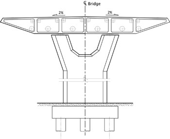
Approach Viaduct Section
The viaduct superstructure is a multi-cell post-tensioned concrete box girder with an outside form matching the arch span girder. The six box cells are each nominally 5.1 meters wide. The four interior webs are the main load-carrying elements and contain longitudinal post-tensioning.
Expansion joints in the bridge deck are located at the abutments only. The viaduct girders are post-tensioned to the arch table to provide a force- and moment- resisting connection with no expansion joint. Thus the girder is continuous over the full length of the bridge.
Y-shaped reinforced concrete piers on pile foundations support the viaduct girders. Each pier consists of a wide vertical shaft, supporting a pair of narrower inclined shafts. The 7.5 meter tall inclined shafts support the box girder at a transverse diaphragm. This pier geometry allows multiple re-use of concrete forms.
Analysis
Bridge Modeling
A 3-D computer model was developed to represent the entire bridge from abutment to abutment. All principal bridge components are represented explicitly, including the foundations, piers, arch bases, girders, arch ribs, arch tie, and hangers. Its geometry reflects accurately the final built geometry of the bridge, and its stiffness and mass properties were evaluated and incorporated so that it can reasonably predict the actual behavior of the system.

Overall View of Computer Model
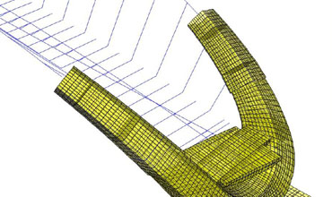
Transition Rib Shell Model
Dead load analysis
A multi-stage dead load analysis was performed with the 3-D model, as means of attaining the final dead load deck profile grade with the correct distribution of load in the hangers and arch ribs. The purpose of the procedure was to provide an estimation of the long-term at-rest conditions of the bridge, with a girder dead load resisted by hanger forces without net bending in the girder, and with statically and kinematically compatible forces and moments in all structural components. The dead load analyses procedures were as follows:
- Performed gravity analysis using element loads for self-weight of deck, arch ribs and hangers, including initial force in the deck tie. Allowed bridge to deform as it may. Recorded vertical displacements of the deck, relative to the arch table, at the 40 hanger locations in displacement vector [U], where [U] is a [40 x 1] vector.
- In 40 separate load cases (for 40 hangers), applied an initial strain to each hanger that is equivalent to 1 kN of tension in the unrestrained hanger. Recorded vertical displacement of the deck, relative to the arch table, from each load case at each of the 40 hanger locations and obtained [F], where [F] is a [40 x40] flexibility matrix.
- Evaluated the [40 x 1] required initial prestress vector [P] using the relationship [P] = [F]-1x [U] where [F]-1 is the inverted [40 x40] flexibility matrix. Converted [P] from an internal force vector to an equivalent initial strain load in each hanger.
- Applied equivalent initial strain loadings to all hangers in one loading. Superimposed this load case with the gravity analysis from step 1, to restore the deck displacements to the final vertical profile grade (zero vertical displacement relative to the arch table), and provide dead load force distributions in all structural components.
Vibration analysis
One hundred modes were extracted in order to validate the model and understand its dynamic behavior. The characteristics of the fundamental five modes are summarized below.
| West Rib | Symmetric out-of-plane sway | 1 | 1.96 |
| East Rib | Symmetric out-of-plane sway | 2 | 1.88 |
| Deck | Symmetric coupled lift/twist | 3 | 1.11 |
| Deck | Anti-symmetric lift | 4 | 1.08 |
| Deck | Symmetric coupled sway/twist | 5 | 1.02 |
Live load analysis
The following four cases of Chinese national standard loading were used for the live load analyses:
- City Class A lane load for maximum moment with uniform load of 10 kN/m and point load of 300kN per lane (CJJ 77-98).
- City Class A lane load for maximum shear with uniform load of 15 kN/m and point load of 300kN per lane (CJJ 77-98).
- Grade Super-20 vehicle loading per lane (JTJ 021-89).
- Grade 120 Trailer loading per lane (JTJ 021-89).
Temperature change analysis
Temperature demands in the girders, hangers, and arch were evaluated by applying a uniform thermal loading to all components. The maximum seasonal rise in monthly temperature at the project site is about 12.2°C, and the maximum fall is 14.7°C. Therefore, a temperature rise and fall of 15°C was assumed for the analysis. In general the temperature demand on the superstructure is small compared to DL and LL.
Wind study and analysis
Static and dynamic wind analyses were performed. Aerodynamic drag coefficients were determined by wind tunnel testing of section models of the arch ribs and deck cross sections. An aerodynamic evaluation of the bridge was undertaken to evaluate the expected aerodynamic performance of the bridge, determine its susceptibility to aerodynamic effects such as self-induced excitation, suggest design revisions to address any performance problems, and estimate equivalent design static wind loads. The following tasks were undertaken to achieve that objective:- Develop appropriate design wind speed criteria,
- Perform wind tunnel tests for loading characteristics of the girder and arch ribs,
- Dynamic computer modeling of the bridge,
- Evaluate a critical flutter wind speed, and
- Estimate the buffeting response of the bridge to a design wind speed.

Deck Section Model

Wind Tunnel
Dynamic analyses using the first twenty vibration modes excited by gust-compatible wind loading was performed to evaluate a dynamic gust factor for use in design. A dynamic amplification (gust) factor of 2.0 was thereby established. The wind demands were found by applying the static wind load forces along with a dynamic scale factor. The static wind pressure on elements was computed as: W = k3 * CD * GF * po Where:
| k3 | = the height coefficient | |
| CD | = the drag or lift coefficient determined by model tests | |
| po | = the baseline wind pressure (600Pa) | |
| GF | = the gust factor to account for dynamic amplification |
Seismic study and analysis
This bridge site is not located in a high seismic zone. But due to the unusual geometry and mass distribution, a detailed seismic study of this bridge was conducted to achieve the following objectives:- Development of performance criteria, identifying two probabilities of earthquake and two performance levels for design checking of the bridge.
- Development of ground motion response spectra for the site, corresponding to 10% and 2% probabilities of exceedance in 50 years.
- Structural modeling of the bridge for static and response spectra dynamic analysis under the project ground motions.
- Static and dynamic structural analyses under various loadings and ground motion combinations to provide an assessment of the conformance of the design with the performance requirements.

Response Spectra
For calculation of force and moment demands, the Safty Evaluation Earthquake spectrum was used with a response modification factor R of 3.5 to account for inelastic behavior and the ability of a structure to sustain damage and dissipate energy without failing. The Functional Evaluation Earthquake was used with a response modification factor R of 1.0 to represent no allowable damage. The envelope of force and moment demands from these response-modified analyses were used for component design and checking. For calculation of displacement demands, the Safty Evaluation Earthquake spectrum was used without reduction. The spectra were applied in the transverse and longitudinal directions, and an SRSS formulation was used to combine the two components.
Design Validation
The structural design of the bridge was validated by comparing the force and moment demands in components under various loading combinations with the corresponding capacities of the components. The demands were evaluated by the structural analyses summarized in the previous chapter. The capacities were evaluated using accepted methods for concrete and steel components. Stresses and displacements were also checked as required.
Construction
Construction Method
The construction sequence employed on the Nanning Bridge will affect the forces, stresses and displacements on the completed structure. For that reason a detailed construction sequence was developed for use in the final design bridge. Construction of the Nanning Arch Bridge will be governed by the following criteria:- The Yong River is a navigable waterway and must remain open during construction.
- Utilization of well-established construction procedures in China.
- Utilization of readily available skilled labor.
- Utilization of readily available heavy construction equipment.
- A maximum required lifting capacity of 120 metric tons.
- Construction safety, speed and reliability.
Construction
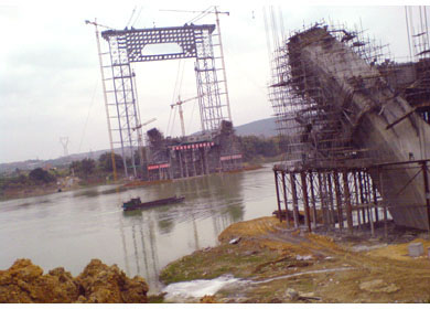
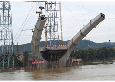
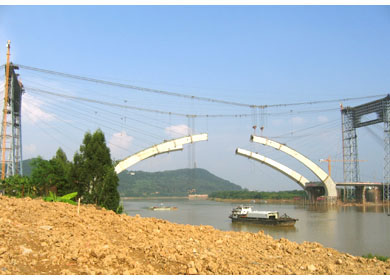
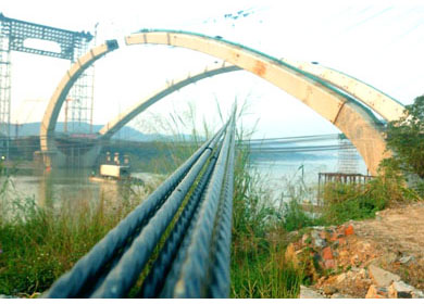
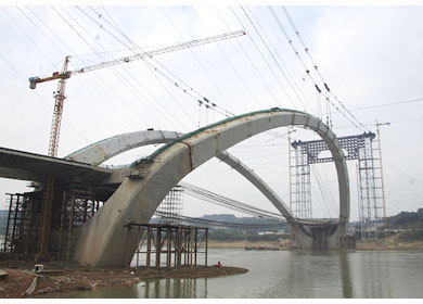
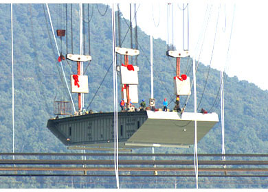
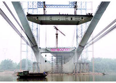
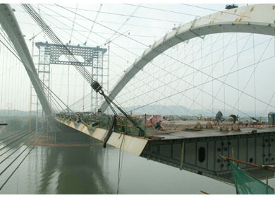
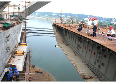
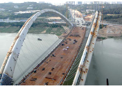
China Railway ERJU 5th Engineering Co. Ltd. was selected to build this bridge. The construction began in early 2005, following the general construction sequence outlined above. The majority of the approach spans and substructure for the main span was completed in 2007. The construction of the arch ribs was completed in November 2008. The construction of the deck was completed in February 2009. Installation of the deck overlay and other works were completed in August 2009.Arch Rib






Deck




Conclusion
The unique design of the Nanning Bridge considers aesthetics, performance, constructability, and economy. The bridge form provides a funicular through-arch to support a curved span. The arch ribs and deck girder balance each other's weight to provide a structure that is both rational and efficient. The design was validated by extensive engineering studies addressing overall static and dynamic system performance, construction sequence, and the strength and serviceability requirements of structural components. The resulting structure can be described as a daring but rational concept, supported by prudent engineering and construction execution. The bridge was opened to traffic on September 21, 2009.

